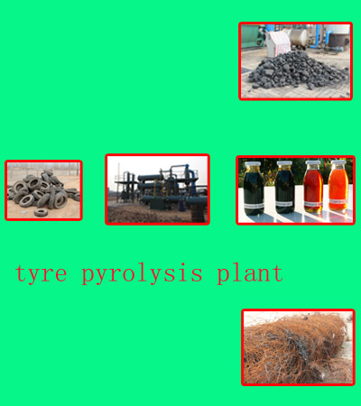
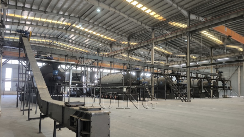
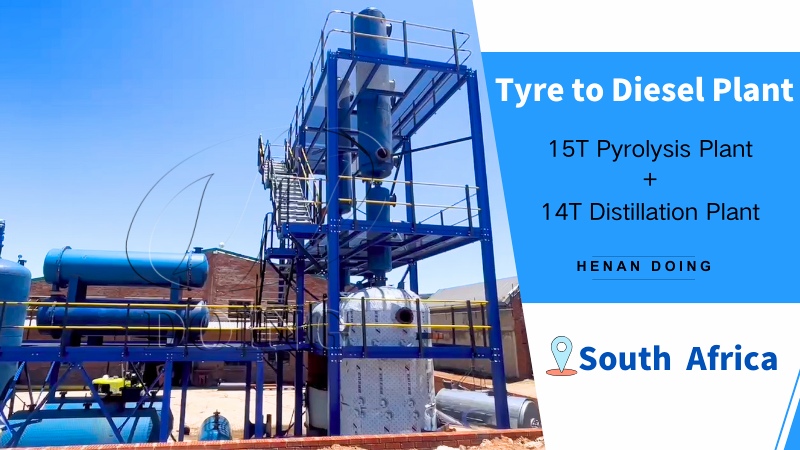
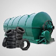
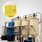
The flow chart of used tyres to oil product introduction

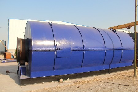
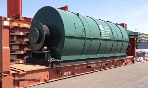
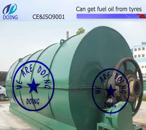
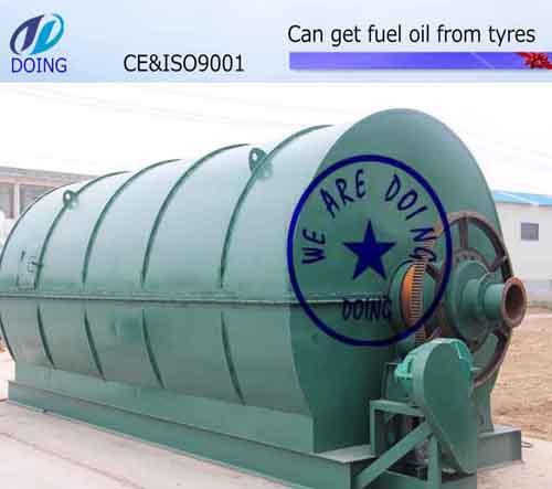
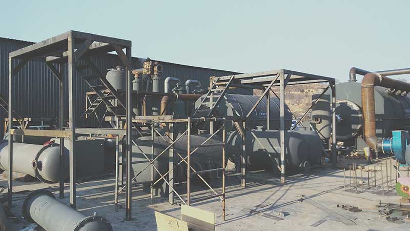
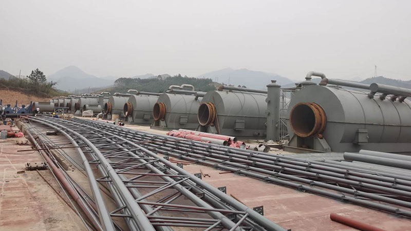
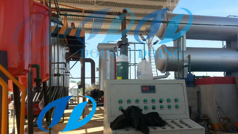
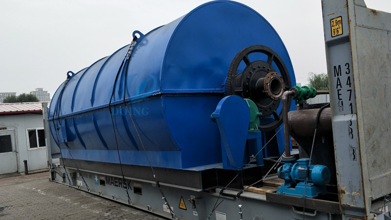
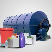
The whole pyrolysis system named waste tire recycling machine is composed by 13 parts, which are reactor, transmission device, catalytic chamber, cooling tube, heavy tank, oil-water separator, condenser, light oil tank, safety device, vacuum system, dedusting system, draft fan, chimney.
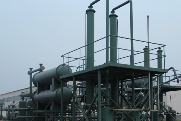
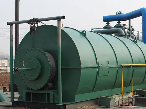
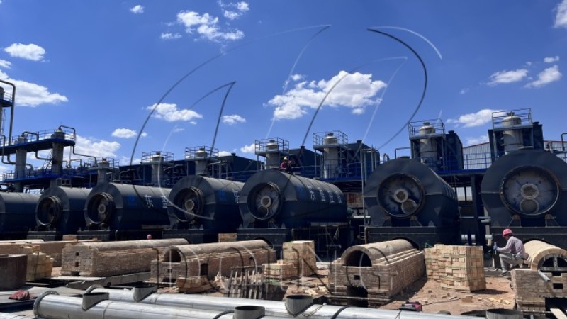
The two keys of pyrolysis plant are reactor and cooling system.
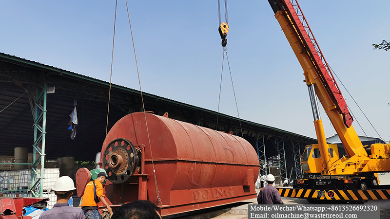
Reactor directly decides the machine's safety and service life. It is made by welded steel plate. So the quality of welding will have a direct impact on safety and service life. Therefore, we use automatic welding machine, X rays detection and heating treatment which will not only guarantee the quality of welding but also greatly improve working efficiency.
For cooling systems, there are two steps. Cooling pipe is the first step. The second is condenser. We have three condensers. And there are 57 pipes in one condenser. Diameter is 48mm for one small pipe. The heat exchanging area is about 13square meters for one condenser. So the total cooling area is about 40 square meters, which will guarantee you a high oil yield.
Technical parameter of DOING Pyrolysis Equipment
ItemsContents
1Equipment typeDY-1-6DY-1-8DY-1-10
2Raw materialtires/Plastictires/Plastictires/Plastic
3Structural formHorizontal rotationHorizontal rotationHorizontal rotation
424-hour Capacity6 ton8 ton10 ton
5Oil yield2.7ton3.6 ton4.5 ton
6Operating pressureNormal Normal Normal
7Material of ReactorQ245RQ245RQ245R
8Thickness of Reactor14mm14mm16mm
9Rotate speed of Reactor0.4turn/minute0.4turn/minute0.4turn/minute
10Total power12KW12KW23.5KW
11Mode of coolingWater coolingWater coolingWater cooling
12Cooling area of condenser40sqm40sqm65sqm
13Kind of transmissionInternal gear driveInternal gear driveInternal gear drive
14Noise dB(A)锟斤拷85锟斤拷85锟斤拷85
15Size of Reactor(D脳L)2200脳60002200脳66002600脳6600
16Working formIntermittent operationIntermittent operationIntermittent operation
17Delivery time20days20days20days
18Weight27T35T45T
| Technical parameter of the flow chart of used tyres to oil | ||||
|---|---|---|---|---|
| Items | Contents | |||
| 1 | Equipment type | DY-1-6 | DY-1-8 | DY-1-10 |
| 2 | Raw material | used tyre, waste plastic, waste rubber, | ||
| 3 | Structural form | Horizontal rotation | Horizontal rotation | Horizontal rotation |
| 4 | 24-hour Capacity | 6 ton | 8 ton | 10 ton |
| 5 | Oil yield | 2.7-3.3ton | 3.6 -4.4ton | 4.5 -5.5ton |
| 6 | Operating pressure | Normal | Normal | Normal |
| 7 | Material of pyrolysis Reactor | Q245R | Q245R | Q245R |
| 8 | Thickness of pyrolysis Reactor | 16mm | 16mm | 16mm |
| 9 | Rotate speed of pyrolysis Reactor | 0.4turn/minute | 0.4turn/minute | 0.4turn/minute |
| 10 | Total power | 19KW | 19KW | 19KW |
| 11 | Mode of cooling | Water cooling | Water cooling | Water cooling |
| 12 | Cooling area of condenser | 100sqm | 100sqm | 100sqm |
| 13 | Kind of transmission | Internal gear drive | Internal gear drive | Internal gear drive |
| 14 | Noise dB(A) | ≤85 | ≤85 | ≤85 |
| 15 | Size of Reactor(D×L) | 2200×6000 | 2200×6600 | 2600×6600 |
| 16 | Working form | Intermittent operation | Intermittent operation | Intermittent operation |
| 17 | Delivery time | 20days | 20days | 20days |
| 18 | Weight | 27T | 30T | 35T |
Pyrolysis oil appliaction
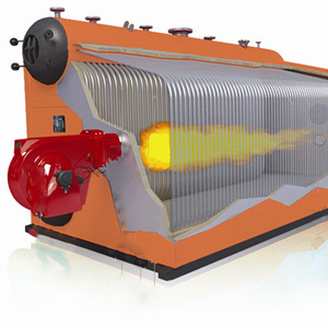
Hot water boiler
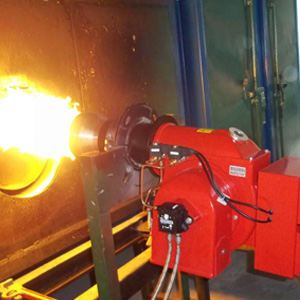
Fuel pump
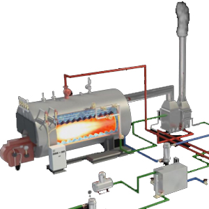
Industrial boiler
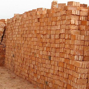
Brick factory
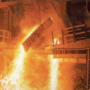
Steel mills
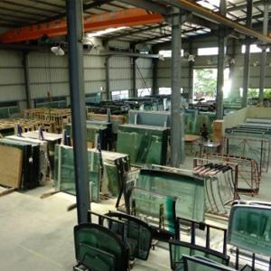
Glass factory